A lot of photometric data in the form of LDT and IES files pass across our desks. The majority of them are problematic.
Lighting designers use advanced tools like Relux and Dialux to produce incredibly detailed lighting designs with near photorealistic renderings of the lighting effects. They use the glare tables and glare calculations in the programs, and yet they base them on bad input data.
One part of the problem (we don’t attach any blame for this) is that the lighting design programs have made it possible to import and use any valid data file. They are quite specific in saying that they accept no responsibility for the quality and accuracy of the data used in their calculations. They must have got so fed up with poorly formatted files being rejected by their wonderful programs that over the years they have made it possible to import virtually anything. We can only conclude that most users believe that, if it imports into Relux and Dialux, it MUST be right; however, nothing could be further from the truth.
Let’s list some of the common things we see in photometric data files used for lighting design.
Uplight that should not be there
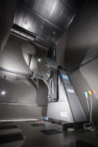
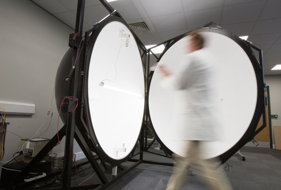
These days most goniophotometers collect data in absolute calibrated intensities, with the lumen output calculated by summing the intensities over the spherical data collection field. Any goniophotometer will measure some stray light during the test as it is impossible to make the surfaces of the test area and the gonio itself completely non reflective. A good well-run laboratory will minimise this stray light, but there will always be some. A properly run lab will carry out a few extra readings to establish the extent of this stray light. With these extra readings it is possible to process the raw gonio data to remove the stray light.

We have seen uncorrected photometric data for sealed-back downlight-only high bay and low bay luminaires with 4-6% uplight i.e. at least 4-6 % over declaration of lumen output. It is actually worse than this as there will also be stray light in the downward intensities, so the ultimate lumen output error will be higher than the non-existent uplight percentage.
Does it matter if there are a few percent of uplight or stray light that should not be there? Well, yes it does:
- Stray light incorrectly increases lumen output so all luminaire efficacy calculations (lumens per Watt) required by the Building Regulations will produce values that are too high.
- Including non-existent uplight in glare calculations when calculating the RUG (UGR) table will produce values in the standard Glare table that are too low.
Incorrect or missing dimensions
We see a lot of photometric data files with missing or incorrect dimensions. LDT files describe 2 sets of dimensions, physical and luminous.
The first set of dimensions give the physical size of the luminaire. Does it matter if these dimensions are wrong? Well, yes it does:
- If physical dimensions are wrong, then your luminaire layout plan is worthless. We are placing luminaires in close relations to other services, sprinklers, AC ducting and vents, signage, etc. If the luminaire size is wrong, then you can’t tell if your layout will work.
The second set of dimensions give the size of the luminous portion of the luminaire. Does it matter if these dimensions are wrong? Well, yes it does:
- The main value dependent on these dimensions being correct is the RUG (UGR) table. If the luminous size is wrong, the values in the standard glare table are incorrect.
- We see a lot of data for luminaires with some light emitted horizontally and upwards where the luminous height in the file is zero in all 4 planes. This is physically impossible and should yield a false glare table; however, lighting design programs do not sense check your data. They perform the calculations and produce values in the standard glare table that are incorrect.
- Glare is a hot (misunderstood) topic present on nearly all specifications. Getting the glare table calculated correctly is very important.
There is another wrinkle here – IES files only describe the luminous dimensions. There is no way for an IES file to provide physical dimensions. There are several problems with this:
If the file is correct, the dimensions in the IES file are the luminous dimensions:
- The physical size of the luminaire is usually larger than the luminous size, so your layout will not tell you if your luminaire bangs into the AC ducts.
- An IES file for a luminaire with no luminous height will have a height/thickness of zero and so will not be visible in your layout from certain points of view, this could be a bit of a problem for suspended or surface downlights.
If the file is wrong and the dimensions are the physical size:
- The luminous size of the luminaire is usually smaller than the physical size, so the values in the standard glare table will incorrect. Increasing the luminous area gives lower values in the glare table. Surely no unscrupulous manufacturer would ever do this to intentionally get a better UGR table? (!!!!)
Lighting design programs offer a workaround for this problem by providing a facility to edit the dimensions of luminaires, but this is an extra step for the lighting planner which can be avoided by using correctly formatted LDT files instead of IES files. There is quite simply less work required to do the job properly.
No symmetry or incorrect symmetry
A photometric data file for use in lighting design is supposed to represent the average performance of an average luminaire of that type (except for emergency lighting products where there are legal constraints).
Most photometric data files we see have no symmetry applied to them. If a manufacturer is developing a luminaire, they would want the test data from the prototypes to be ‘warts and all’ so they could see if it has been manufactured correctly. If the luminaire is meant to have some symmetry and the test data does not, either the test set up was incorrect or the test sample was wrong. Either way, as a developer, they would want to know.
Photometric data released to clients/users should be the average/mean data of the production run of that luminaire which requires a symmetry to be applied. Not only does this give the necessary average performance, it will show the product in the best possible light (no pun intended) as the design will show the expected symmetry. It seems this distinction between development data and product data has been lost, and most labs are only issuing non-symmetric files and leaving the manufacturer to apply any symmetry.
Too much / not enough detail
Photometric tests should be performed using data steps small enough to record the full details of the luminaire distribution including any unexpected anomalies. Routine tests would be in 1° steps in elevation and 5° steps in azimuth with the ability to reduce this step size when required. This is test data – it is not suitable for release for use with lighting design software.
Lighting design programs calculate the average effect of a luminaire over a small area, then repeat the calculation for the next small area. The size of the area is determined by many parameters but is typically in the range of 0.2m2 to 10 m2. Visual representations and maximum and minimum values are obtained by using the results from each of these areas, while the main calculations are based on the combined effect of all these small areas in the lighting scheme. Each area requires the calculation of an average intensity from the luminaire at various angles. The more detailed the file the longer, it takes to calculate the average.
The released data for lighting design purposes should have the correct data steps appropriate to the distribution.
For instance, a dense opal downlight luminaire that has an almost perfectly Lambertian distribution (output is proportional to the cosine of the angle) can be described with 19 data steps (0° – 90° in 5° steps, each elevation angle is relevant to all azimuth angles). This is a small calculation load for the program.
If a test data file is provided with, say, 0° – 180° in 1° steps in elevation and 5° steps in azimuth, the program must calculate not from 19 data steps but from 13,032 data steps which increases the calculation load on the program and so slows scheme calculation down without having any effect on the accuracy of the calculation. Providing extra detail is not harmful, but it is wasteful and unnecessary and will slow the light planner down.
Trying to design with a symmetric 10° FWHM (Full Width Half Maximum) spotlight with 5° elevation data steps is wrong, misleading and potentially very inaccurate. There would only be 3 data points that are significant – 0°, 5° and 10° – with no detail about what happens between each point. This luminaire would require data in 0.5° or possibly 0.1° elevation steps to describe the beam shape correctly.
A lot of LED streetlights have very sharply delineated peak intensities in elevation over a relatively small azimuth spread. The old CIE streetlight data format expected variable intensity steps in both azimuth and elevation with maximum detail being 2.5° in elevation and 5° in azimuth over the peak with, relaxing to 15° in both directions well away from the peak. We have seen LED streetlights that require even smaller steps in both planes.
Missing the peak intensity due to wide data steps in streetlighting is very poor practice. It results in incorrect values for threshold increment (TI) and both longitudinal and overall uniformity. The same requirements for detail apply to narrow beam flood lights and some extreme emergency luminaires that have a very narrow peak and a sharp run back above and below the peak.
Don’t forget designers have statutory responsibilities under safety legislation when designing emergency lighting installations and can be held criminally responsible for their designs. Missing peaks and troughs in the data will also result in lumen output errors and therefore incorrect results for luminaire efficacy calculations (lumens per watt) required by the building regulations.
A polar curve showing straight lines is a pretty good indication that the data steps are too wide to correctly describe the luminaire. If a detailed file shows a very jagged polar curve, the lighting designer may decide not to use that luminaire in a scheme as the visual effect when installed may result in stripes on the floor that are not shown in the average calculations of the lighting design program but result in end user complaints.
File name & catalogue number
We believe it is a relatively simple matter to make the file name and catalogue number match in some way. This makes it easy for designers to find a particular product data file from a list.
We see a surprising number of files where the file name has no relationship to the catalogue number. In some cases the catalogue number and file name that are supposed to match are different, so the lighting planner cannot be sure which data to use. Manufacturers and laboratories should make it easy for designers to find and verify your data and be sure which product it refers to.
Whilst we are on the subject, another peeve is ridiculously long file names/catalogue numbers. Exporting LDT files from a particular website produces catalogue numbers of 300 characters and more. The LDT file format specifies a maximum of 78 characters for luminaire name and luminaire number. The subsequent ELX format specifies a maximum of 24 characters. The default maximum expected length for lighting design programs is now 40 characters. While lighting design programs may tolerate more characters, they often do not have enough room on the screen to display everything.
The LDT file format specifies a maximum of 8 characters for the file name. The subsequent ELX format specifies a maximum of 12 characters. While both limits are currently ignored by lighting design programs, there are still several applications that stick to the Windows path length and line length limit of 256 characters. It’s annoying to have to edit the file name / catalogue number just to read the file, and it means lighting designers are required to do more work to use a particular product. Perhaps this is us being ‘old school’ as we were brought up on 8.3 format for file names, but if you need more than 20 characters for a file name or catalogue number then perhaps you are not really in control.
You might think none of this really matters. The files downloaded go into Relux and Dialux and produce answers, so why all the fuss? As a supplier to designers and users, shouldn’t manufacturers and test laboratories ensure that the data presented is in the best possible format to help their clients make effective and efficient use of their products?


